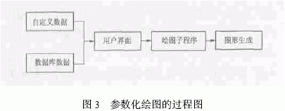
Die-casting CAD system is a computer-aided design software that integrates mold design and drawing. It eliminates the cumbersome calculation, design and drawing, which reduces the work intensity of designers, greatly shortens the mold design cycle and improves the reliability of design results. Sex. 1 Development of Die Casting CAD Technology The development of foreign mold CAD system has been 30 years old. The CAD system of die-casting mold started late compared with other types of mold CAD system. However, it can effectively draw on the development experience of other mold CAD systems, so it has developed in recent years. rapid. The early die-casting CAD system only selected the die-casting process parameters, and only used the computer's calculation function to reduce the designer's work intensity, and did not fully utilize the computer's engineering application. In addition to calculating and selecting the design parameters of the die-casting mold, the higher-level die-casting CAD system can automatically generate graphics and output graphics, and can simulate and analyze the die-casting process, and output the NC machining program to form a more complete die-casting mold. CAD/CAM system. Metflow, a CAD/CAM application software for die-casting gating systems developed by the Commonwealth Scientific Industrial Research Institute (CSIRO), provides a CAD/CAM system for the design analysis and manufacturing of gating systems. CADDES, a computer-aided design engineering system for die-casting molds developed by Toyota Motor Corporation of Japan, has been put into use. Domestic research on die-casting CAD technology began in the mid-1980s. In 1984, Shenyang Foundry Research Institute launched a computer-aided design software for small and medium-sized mixed flow runner single casting blade riser system, which is a software system that is in line with CAD concept in China's foundry industry. Since the 1990s, China's die-casting CAD technology has made great progress, and the development of standardized CAD/CAE/CAM software technology for die-casting molds has been carried out. 2 Basic structure and function of die-casting CAD system Die casting molds are made up of many stencils and parts. A complete die-casting CAD system should consist of four main parts: operating system, graphics software, database, and application. The Windows 2000 operating system, AutoCAD 2000 graphics software and Access 2000 database were used, and the second development of AutoCAD 2000 was performed by Visual Basic to design the die-casting CAD system. The die-casting CAD system controls the various parts by designing a multi-layer menu method to realize man-machine dialogue and transfer. The main control menu interface of the die-casting CAD system is shown in Figure 1. The functions of the main menus at each level are as follows. (1) System Management Menu This section mainly manages users who use the software, including adding users, modifying user passwords, and so on. (2) Process parameter determination menu This part is mainly to estimate the volume, mass and parting surface projected area of ​​the die casting, determine the injection specific pressure and filling speed, calculate the cross section of the gate, and select the die casting machine model. Check. The flow chart is shown in Figure 2. (3) The gating system design menu completes the selection and determination of the basic dimensions of sprues, runners, gates, overflow troughs and vents suitable for different types of die casting machines, as well as the cross-sectional area, volume and Calculation of parameters such as quality. (4) The shaped part design menu determines the parameters of the forming part and designs the cavity and core. (5) The mold frame design menu completes the design and drawing of the inserts, moving molds and fixed mold sets, support plates, moving molds and fixed mold base plates, guide columns, guide bushings, etc., and finally obtains a more complete formwork diagram. . (6) Introduce the determination and calculation of the basic dimensions of the mechanism design menu putter, push plate, push tube and unloading plate, and draw the part drawing. (7) The core pulling mechanism is designed to calculate the core pulling force and the core distance of the menu core, and draw the parts drawing of the inclined guide column and the slider. (8) The Help menu mainly provides users with some help in using the software. 3 Parametric design in die casting CAD system The traditional CAD drawing software uses the computer and peripheral equipment as the drawing board. It adopts man-machine dialogue mode to generate graphics by manually inputting various commands and parameters. To modify the graphic content, only the original lines are deleted and then redrawn. For the design of shaped industrial products, it is generally necessary to form a series, which requires the CAD system of the product to have a parameterized design function to realize the automation of the size-driven graphics. The process of parametric drawing is shown in Figure 3. This system uses Visual Basic for secondary development of AutoCAD, which is based on the new Activex automation interface technology. AutoCAD Activex technology allows users to control and manipulate AutoCAD from within or outside AutoCAD through other applications, such as Visual Basic, through the information exposed by AutoCAD. The system uses the Visual Basic language to write a general drawing program for serialized parts, calls AutoCAD drawing, and then draws and outputs graphics in the AutoCAD environment. Because the parameterized dialogue function is used in the drawing program, Visual Basic's design idea for AutoCAD parametric drawing is realized. Due to Visual Basic's visual development environment and rich control support, the main control menu is programmed with Visual Basic in the CAD system of the die-casting mold. In the die casting CAD system, various process parameter databases, such as die casting machines, are invoked by running process parameter determination module, casting system design module, forming part design module, mold frame design module, launching mechanism design module and core pulling mechanism design module. Model database, mold frame size database, launching mechanism and core size database to achieve mold design and graphic drawing. 4 Conclusion The CAD system of die-casting mold was designed and integrated. The process parameter database was established by Access 2000, and the second development of AutoCAD was carried out with Visual Basic. In the process of system development, the design idea of ​​Visual Basic for CAD parametric drawing was fully utilized. Through the secondary development of AutoCAD, this universal software can be made more professional and intelligent.
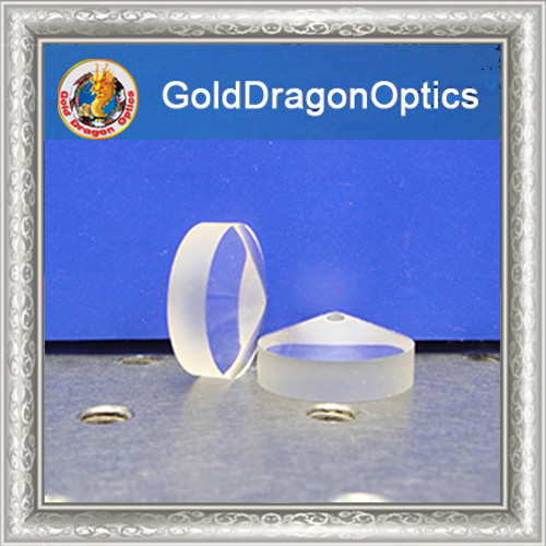
Fused Silica Axicons,mexican mask ,axicons, acxion diet pills,axicon lens, axicon rainbow window suncatcher, axicon pills
Our company can produce a variety of specifications, radius, different base materials of flat convex Spherical Mirrors flat convex spherical Mirrors, flat concave spherical mirrors, double convex spherical mirrors, double concave spherical mirrors, meniscus spherical mirrors and other ordinary spherical mirrors. Special spherical mirror can also be processed, such as: achromatic spherical mirror, aspheric surface and spherical mirror group. Bandwidth Of Low Pass Filter,Bandwidth Of Photodetector,Abandwidth Equation,Bandwidth Low Pass Filter Gold Dragon Optics Electronic Technology CO.,Ltd , https://www.golddragon-optics.com


Materials: optical glasses such as flint glass, ultraviolet fused quartz and infrared fused quartz, as well as optical crystal materials such as calcium fluoride (CaF2), germanium (Ge), Zinc selenide (ZnSe) and silicon (Si)
Focal length: ±5mm -- ±1000mm±1%
(Germany TIROPTICS OPTOMATIC2000 test)
Outer circle: 4mm -- 200mm±0.1mm
Center thickness tolerance: ±0.1mm
Center deviation: 3-5 points
Surface accuracy: /2@
Surface quality: 40/20
Effective diameter: 90%
Plating film: according to customer requirements can be coated
In addition, we have more than a thousand kinds of standard products, and some of the standard products in stock to meet your needs

Research on CAD System of Die Casting Die
