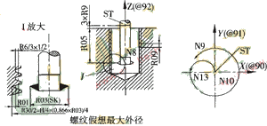
3 programming The definition and trajectory of the initial assignment parameters of the program Figure 3 is the internal thread cyclone milling program trajectory and parameter definition: RO1 - the nominal diameter of the machined thread; Previous page next page
Take the Siemens 8 system as an example to introduce the preparation of its NC program. Written in a subroutine. Using the R parameter instead of the number and value in the statement can be applied to thread processing of different diameters, different pitches and different depths, and has certain versatility. The program is programmed according to the tool center path, so there is no need to use the tool compensation function. The program can be stored in the machine. When in use, it is called by the main program and gives the amount of cutting and initial parameter assignment. At the same time, the tool center is positioned above the finished bottom hole. 
Figure 3 Internal thread milling work diagram and parameter definition
R03—special milling cutter cutter tip diameter (SK);
R05—the depth of the machined thread;
R06—the tolerance value of the thread diameter;
R08—thread milling distance;
R09—pitch;
R11—Tool axis number (X axis, 111=1; Y axis, 111=2; Z axis, R11=3).
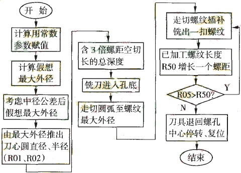
The block diagram of the internal thread milling block diagram on the XY plane for internal thread milling on the XY plane is shown in Figure 4: 
Figure 4 program flow chart
Cyclone milling of large internal threads (2)
