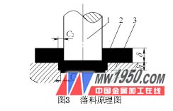
The blanking process is one of the oldest and most widely used methods in stamping processing, that is, using a stamping device to apply pressure to the material between the molds, so that shear deformation occurs at a certain gap edge, and the breaking process is separated. The basic processes of ordinary punching are mainly punching and blanking. In terms of the quality of the blank, it mainly refers to the section and precision of the blank. Among the four components of the cross-section of the blank, more attention is paid to the shear plane, the fracture surface and the burr. In actual production, it is mainly desirable to obtain a higher shear plane for the blank. Ordinary punching is difficult to achieve when certain parts have a height requirement beyond the normal punching of the cut surface. In order to improve the cross-section quality of the blanking parts, especially the height of the shearing surface, in the history of more than 100 years, there have been some special stamping processes, such as refurbishment, precision blanking and semi-precision blanking. However, it is required to increase the number of processing steps or use of valuable equipment, which is incompatible with the production status and target requirements of most enterprises. In actual production, due to some blanking parts, especially thick plate blanking parts (such as steel ring spokes, etc.), the cross section does not require a full shiny cutting surface, but only the shearing surface can be stabilized in the material thickness 1 /3 or more; and based on economical considerations, most of the above methods or methods of increasing the height of the shear plane are not desired, and it is desirable to use a simple separation method of ordinary punching as much as possible. However, ordinary punching is difficult to obtain a high shearing surface even under a reasonable clearance condition, especially for a thick steel plate member having a large hardness. Therefore, there is a need for a blanking process capable of stabilizing the shear plane of the section of the blanking part in the normal blanking condition by 1/3 or 1/2 or even 2/3 of the thickness of the material to solve the automobile steel. There is an urgent need for the processing of the hole shape of the spoke hole and other product parts. To this end, we have proposed a new method of punching. 1. New process principle The new method combines the deformation characteristics of ordinary punching, refurbishing and extrusion, and the deformation principle is a combination of these three processes. For punching, the punch is designed into a continuous step shape, the height h of the step is 1/3 to 1/2 of the material thickness δ, and the concave mold is a conventional shape; the gap is a positive gap, wherein C1=(2) % ~10 %) δ, taking C2=(12.5 % ~20 %) δ; after the blanking is completed, a complete thin ring scrap is dropped along with the punching waste. The punching principle is shown in Figure 2. For the same reason, for the blanking, the concave die is designed as a continuous step shape, the punch is a traditional shape, the process parameters are selected similarly to the punching, and a complete thin waste is generated. The blanking principle is shown in Figure 3. Next page
As is known, the cross section of a conventional blank is composed of four parts: a sag angle, a shear plane, a fracture surface and a burr, as shown in FIG. 
According to the six stages of the punching deformation process analyzed by meso-mechanical analysis, the formation mechanism is as follows:
(1) The sag angle is the compression of the punch to compress the material and continue to be pressed into the shear material.
(2) The shearing surface is mainly formed when the metal material is pressed from the shearing stage until the crack begins to occur, that is, the plane into which the punch is pressed into the material, and the material is in contact with the side of the punch while being squeezed.
(3) The fracture surface is formed during the punching deformation process because the crack continues to expand until the upper and lower cracks coincide.
(4) The burr is generated by the crack on the side of the tip end of the convex and concave die, that is, the burr is naturally generated during the crack growth stage of the punching deformation. 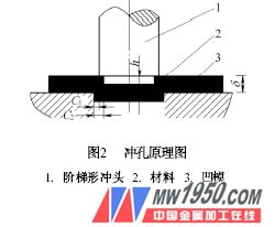
A new method to improve the height of the shear plane of the blank of the blank